So today I thought I’d try my hand at Voxel rendering. Rather than existing in a 2D image plane with an X & Y coordinate Voxels exist in 3D space with a position in the X, Y, & Z axes. A prime example of the use of voxels in rendering is the popular game Minecraft. In Minecraft randomly generated terrain is modelled as large fields of voxels with each voxel rendered as a textured cube. Because the terrain is not just a surface coated in triangles but rather a volume with internal data, the terrain in minecraft can be modified and changed during runtime with little effect on performance.
Voxels are useful for displaying other kinds of volume data too. CT Scans are medical images which capture 3D density plots of a patient’s body. By capturing density at each location throughout the scanned tissue the data can be replayed using a computer to literally look inside the body and see where possible irregularities and illness may reside.
2nd year CT Scan coursework
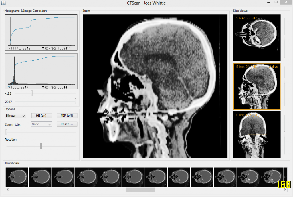
In my second year at university I was given a Computer Graphics coursework to read in and display the data for a CT Scan. It was very low resolution, only 256 * 256 * 113 voxels in size but it worked well for the purposes of the coursework which was simply to demonstrate the ability to parse the volume data into usable slices (not that hard). There were several bonus sections to the project such as histogram equalization and density bounding to eliminate tissue we didn’t care about. Another one of the bonuses was for rendering the volume data in 3D with a hint of using trilinear interpolation. At the time the work load we were under was horrendous due to the year long group engineering project, so while I eagerly completed all of the other bonuses I just didn’t have time to get 3D working. Until now.
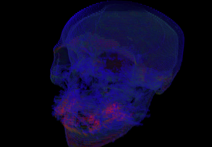
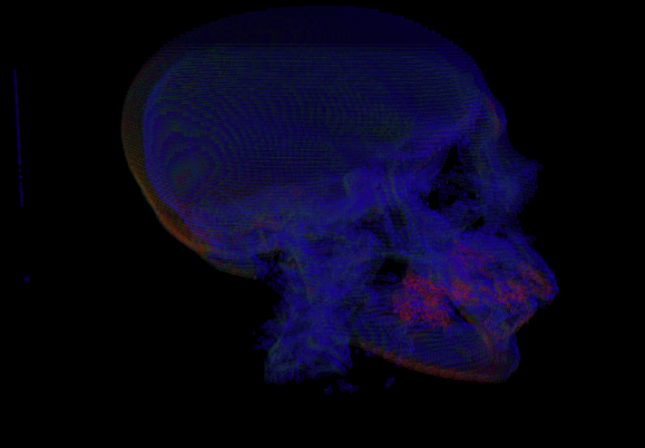
It’s not pretty, and in fact it’s really not pretty when you make it 3D due to the low input resolution of the scan. But there it is! The same CT Scan now rendered in 3D in OpenGL. I used the Java bindings for OpenGL (JOGL) so I could use the same loader code I wrote in 2nd year to parse the binary CT file into a 3D array of shorts.
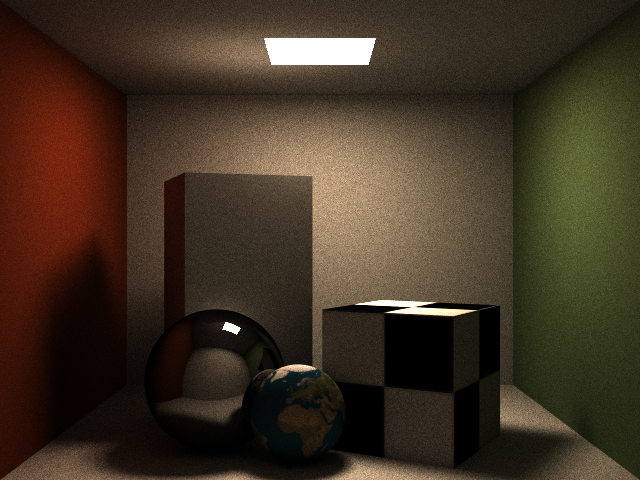
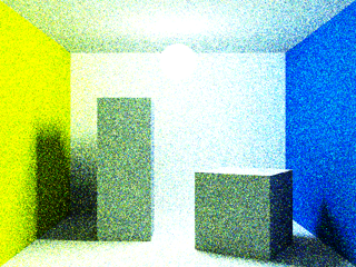
So I’m back to working on this again.. It’s a lot better than before but it’s not perfect. I’m still using unweighted samples during path generation and I am still generating a fresh path (highly randomized in path traced -> light traced construction) for every sample. Because of this the noise that still persists in the image above will never feasibly go away. Today I plan to look at “Multiple Importance Sampling” a lot more in depth.
This morning I was neck deep in code writing a Bi-Directional Path Tracer and this evening I’m building a 3D Printer out of Lego… If only I had the attention span and patience to actually finish a project before starting another. Oh well.
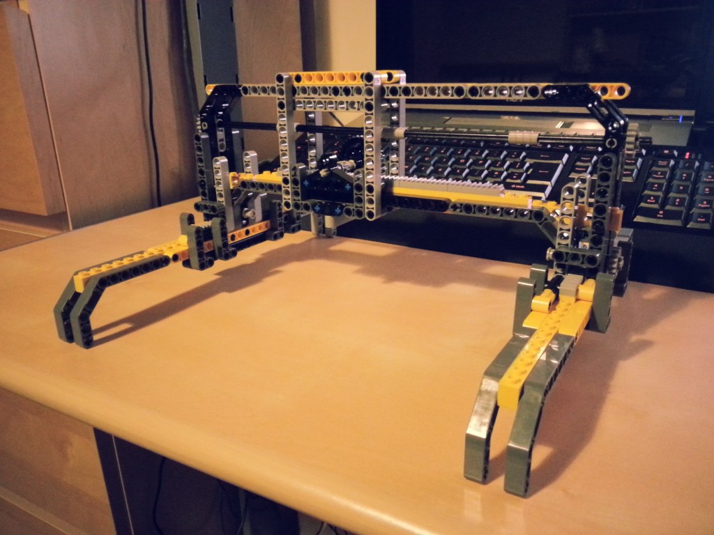
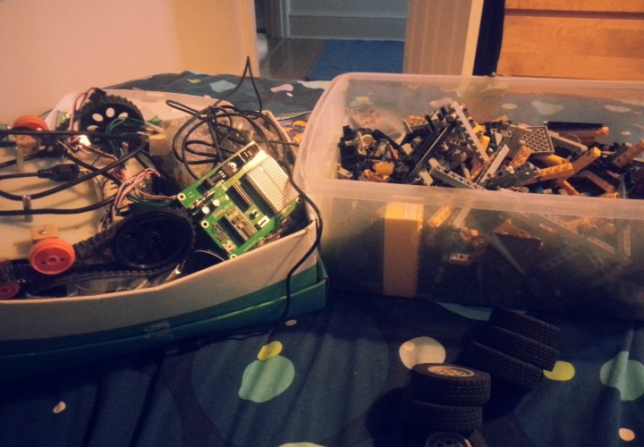
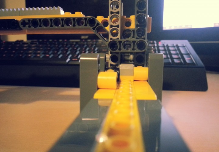
Continuing on from my previous post, in the end I actually trudged down the garden to the shed and pulled all my old Lego Technic out of storage. A quick session of sorting out what kind of bits I had and then thinking about how I could adapt the designs I had bad in CAD to work within the limitations of those parts I decided to just delve in and see what I could make. I was surprised at how much Lego I actually had, but then again my family was always really into Lego & Meccano; and I was quite fond of Knex too come to think of it.
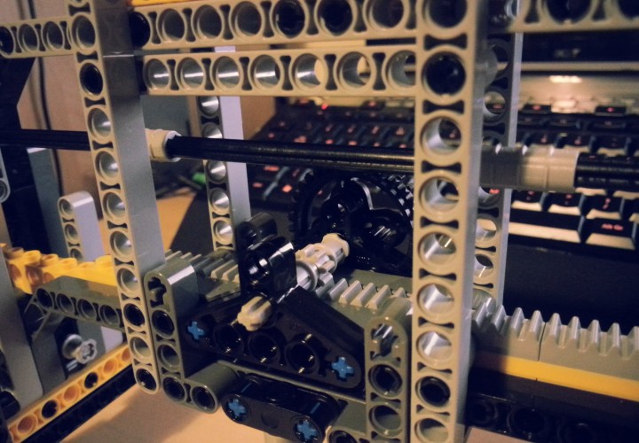
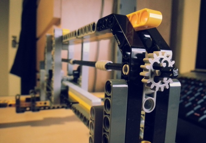
As it turns out the amount of Lego Technic I do have is more than enough to build the frame and mechanics for the first two axes of the Printer. There are some crucial areas however, where I have ran out of very important bits needed for this specific application. For instance the flat toothed strips used to make the tracks for the carriages to walk on were in short supply. I managed to place them on the top carriage such that the X axis gondola can fully utilize them with no waste. However after laying the X axis track there were only four of the tooth strips left; meaning that for now each side of the Y axis tracks only has two toothed segments. I’ll need to get more of them to finish the Y axis along with some gears and extra chain for connecting the cross axle to the walking gears.
It was possible to make some improvements to the initial design during this first build step. Namely the Y axis walker which holds the X axis and gondola is considerably thinner than in the original design, however the gondola still has nearly the same amount of movement. This was achieved partly by making the two connections to the Y axis tracks thinner than their originals, which allows the gondola to travel much closer to the ends of the track. The condensed size also keeps the frame more rigid than a wider variant would have been.
A month or so before I found out I would be starting my PhD in October I was still under the impression that I would be doing an MEng and with it another dreaded dissertation project. This time however, the project would be to do with a software engineering problem, as opposed to last years which could be either industrial, research based, or software engineering.
After much deliberation looking at the shockling short list of projects I decided that I didn’t particularly want to spend a year working on any of them. Not that they were all bad per say, just that if you’re going to spend a whole year working on a single project you best be sure you care about it.
One thing that did interest me about the projects however, a few of them involved using Arduino and embedded systems. This got me thinking, what could I do with Arduino that I could propose as my own project idea? Inspiration didn’t take long, that night I stumbled across this gem while watching random videos on Youtube.
I loved it straight off, to use Lego Technic and Mindstorm NXT to create a working CNC machine! Perhaps this would make a good masters project?
Alas the the project is very much closed source and even the designs for the machine are not available.
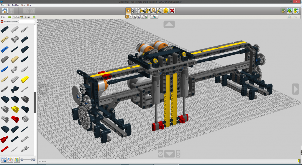
I have however, been able to reproduce the design of the machine and it’s mechanics in 3D using Lego’s 3D Autocad software, Lego Digital Designer. This was a long and painstaking process of taking screenshots of the above video and blowing them up to see the finer details (thank god for 1080p Youtube streaming) and mixing this with my methodology for how I would build this machine if I was given an unlimited set of lego. The result of my reconstruction can be seen below. While it is not a complete build (I omitted the static Y-Axis track that the carriage pictured would ride on), it is the technical majority of the machine.
I believe that this design can even be further improved upon to use less lego while allowing for a larger and more stable device to be constructed. The main limitation with increasing the track size of the device in it’s current configuration is finding a way to proportionally increase the size of the Z-Axis (vertical). Currently this axis uses two Lego Technic linear actuators to move the tool carriage up and down. However, the actuators have a fixed and limited range of climb which cannot be altered. A difference approach might be to use a threaded bar configuration to make a track which moves up and down instead with a small tensioning system to remove vibration and slack from the printing.
After a minor crisis that I am horribly unprepared to start my PhD in October I thought I’d try to delve back into the world of graphics with something simple (ha). I decided to try and extend my Java Path Tracer to support a rendering mode for Bi-Directional Path Tracing. Something which I now realize is easier said than done. Ideally if I had had the time I would have introduced Bi-Directional Path Tracing (BDPT) to my dissertation project last year; however, I simply never had the time to wrap my head around all the mathematics so I left it out.
The image above was rendered at 640 x 480 but I have downsampled the image here to 320 x 240 to make up for the fact I was only able to render 100 samples before my computer BSOD’d. That’s right, because if you can make a Java program cause a BSOD then you know something is terribly amiss. My theory is that it’s simply too much recursion for the JVM. Even though I am running the 64bit version with an increased memory quota the stack for function calls is still (annoyingly) a memory limited 32bit stack. And seeing as this is just a toy project I am working on whenever I start to panic about next year it doesn’t seem worth spending the time to convert the whole thing to an iterative renderer from a recursive one.
I’ve been meaning to do it for a while but I have finally gotten around to making a Template for OpenCL & OpenGL Projects in Visual Studio 2012.
The host application is written in C++ using GLew and freeGLUT to interface with OpenGL, and the Amd APP SDK to interface with OpenCL as I am running a ATI 5850 GPU. Building upon the template is fast and easy and really comes down to just a few core functions which differ for each program. Below is a simplified version of the functions each program must implement.
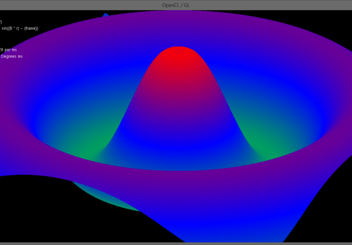
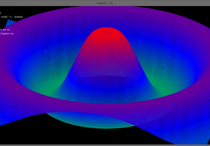
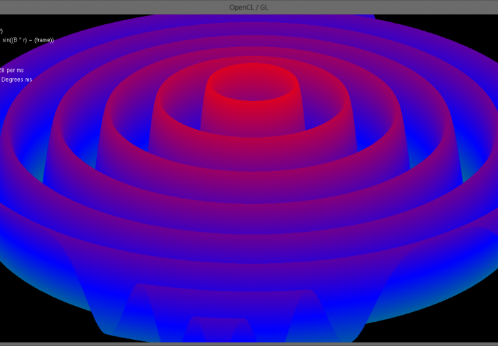
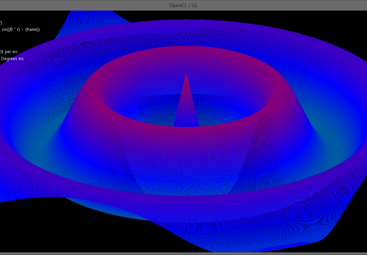
Using this frame as a base to build off of I was able to quickly and easily get a demo running. The program in the video above and the images below generates a 1000 * 1000 (1 million) vertex triangular mesh and displays an exponential sine function over it. At each frame OpenCL computes the 3D location of all 1,000,000 points in the mesh which OpenGL then renders. Due to the massively paralleled nature of the OpenCL update code frame rates exceeding 100 frames per second are achieved! (In the video Fraps capped the frame rate at 30fps for smooth capture)
Below is a simplified version of the SineMesh Demo, most of the work is performed in the initialization phase to create the 1000 * 1000 mesh and link the triangles together. The program could be made a lot more efficient if the triangle linking phase was done such that it creates a Triangle Strip as opposed to the current Triangle List. A strip has the benefit of chaining touching triangles together to save the number of vertices which need to be stored in the linking array.