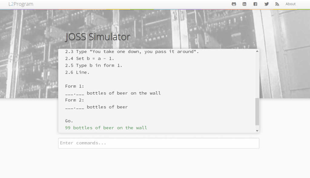
Progress on the JOSS language simulator is coming along nicely. I decided to take a break from transcribing and converting the grammar so I could work on the ui for a bit. This will be helpful as soon I’ll need a way to parse input commands and output the system replies.
So far the terminal is designed along with the input bar. Upon pressing enter the currently written command is added to the bottom of the terminal feed and (if necessary) the terminal is smoothly scrolled down to it’s new bottom. Like the original typewriter consoles on JOHNNIAC, inputs typed by the user appeared in black type and responses from the system are shown in green.
Further plans for the ui are to eventually include some form of modal or accordion based content organisation to allow a pane describing the history of JOHNNIAC, and a pane to describe the syntax for the language.
As I alluded to at the end of my last post on the subject of the JOSS programming language, my goal is to revive the language and create a usable version of it. (Why, you ask? Why not)
The design for the Simulator is to construct a webpage with a black/green terminal style display with a text box at the base of the terminal to allow command statements to be prepared and submitted to the system. On the backend the simulator will run entirely in Javascript, utilizing the PEG.js parser builder to tokenize and execute commands.
When a command is submitted to the terminal it will be given to PEG.js to parse and turn into a syntax tree of tokens. PEG.js also gives very precise parse errors which will allow the simulator to give the user feedback on their commands. If a command is successfully parsed the parse tree and the text version of the command will either be stored as as elements in the “program tape” a javascript object of the form:
By expressing the entire program and state of the simulator in JSON we gain the ability to easily have access to any part of the program or data. We also have the ability to save the current session using the browser’s local storage api or share the program by simply saving the serialized JSON to the server with a unique link. JSON is also the reason for storing the parse trees as objects rather than compiling them to an intermediary before use. By walking and evaluating a command by climbing through it’s parse tree we can use recursion to jump to other commands in the program tape. When we have fully climbed back up the tree to the root node or a command returns the Stop. token we know the program has finished executing.
One problem I see currently is that the language is based around the use of fixed precision arithmetic using 9 decimal places for precision. Currently I don’t know of any way to do math in fixed precision in JavaScript short of rolling my own set of maths classes, and I’d really rather not. For now we’ll work in standard floating point and see if it can be added in later.
The Grammar
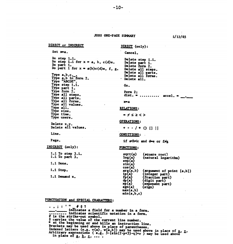
Citation: "JOSS: Experience with an experimental computing service for users at remote typing consoles", J. C. Shaw, May 1965, Page: 10
Using the paper I found previously discussing the use of JOSS on JOHNNIAC over a 16 month period, I have been able to piece together a Context Free Grammar. While I am pretty happy with it, it’s not perfect. Every now and then I spot an error and fix it but for the most part I’m satisfied it’s solid.
There are however a couple of things intentionally in there which aren’t perfect but there is good reason for them. For instance, because JOSS lacks the ability to have user defined functions I have created a function token and within it an array of tokens, each representing a different standard math function available to the user. The reason for this is to allow parse time error checking of the number of variables.
Converting for PEG.js
So far I have gotten numbers and math expressions converted into a PEG.js parser. The current state of the parse can be seen on this Gist along with the BNF Grammar. Eventually I will move all of this into its own repo on Github but for now it’s all being developed in the browser; that is, I’m writing the PEG.js parse directly into their online compiler to test it as I go, so there is nothing local to save to a repo at the moment.
Below is the current BNF Grammar for the language.
My name is Zaphod. Or at least, if my father had had his way my name would be Zaphod.
As the story goes my mother, still light headed and exhausted from child birth had to up and run down to the reception office to stop my father from having the name Zaphod (as in Zaphod Beeblebrox from The Hitchhiker’s Guide to the Galaxy) put on my birth certificate.
Now as uncommon and strange of a name as Zaphod is my parents compromise on the name Joss is arguably just as uncommon. In fact, the only reason you have probably heard the name Joss is because a large proportion of the few people called Joss are famous (no pressure or anything). Joss is also commonly (cough: incorrectly) used as a shortening for Jocelyn.
However, what if my father in fact had another trick up his sleeve? A plan so cunning and dastardly that my mother never would have suspected his evil doing. What if my father named me after a programming language…? He had the knowledge, being a mathematician and programmer at Aldermaston, and he had shown the capability by attempting to name me after a character in a Sci-Fi TV / Radio show & Book series.
The JOSS Language
Today by random happenstance (no I was not Googling my name… who on earth does that? …) I discovered a Wikipedia page about a programming language called JOSS.
JOSS was the child of a 1950’s R&D firm called RAND which quite unimaginatively stands for Reasearch ANd Developement. RAND was funded by the US Army Air Corps which later became the US Air Force, and is still an active organisation today.
RAND developed a computer called JOHNNIAC in 1953. JOHNNIAC, which stood for John v. Neumann Numerical Integrator and Automatic Computer, was soon surpassed by faster and more reliable machines. This however, allowed for other non performance critical research to be carried out on JOHNNIAC; most notably the development and usage of the JOSS programming language.
The JOHNNIAC Open Shop System, JOSS, was the first language which allowed for interactive and concurrent access to a computer. Developed between 1963 and 1964 by Cliff Shaw (inventor of the Linked-List), JOSS allowed for up to eight users to access JOHNNIAC simultaneously via separate typewriter terminals.
The language was designed as a way for mathematicians and engineers to perform small but complicated calculations quickly without having to have a great knowledge of computers or direct access to a “Computer Expert”. JOSS has two methods of interaction, direct and indirect. In direct mode the user presents command statements to the terminal (which were printed in black ink) and JOSS replies to these statements as each arrives (printed in green ink). In indirect mode the user queues up commands by preparing a program, the user then types Go. or types a statement to be run as an initializer which then runs the program.
So was I named after a programming language?
JOSS is openly referred to as JOHNNIAC’s legacy. As it just so happens my father is named John, and by being his only son I am by very definition his legacy. Coincidence? I think not!
After a little more digging trying to find out more about this language I stumbled across this paper published by the RAND Corporation in 1965, describing the results of using JOSS on JOHNNIAC over a period of approximately sixteen months. From this paper, which also gives a good overview of how to use and program in JOSS, a couple of quotes stuck out to me.
People adjust their lives to fit around JOSS… No use coming into RAND before 10:00 am when JOSS arrives, in fact noon or after 5:00 pm is a better time, JOSS is less busy. When JOSS starts typing answers, the titillating pleasure is equalled only by the ensuing anguish when JOSS breaks off into jibberish or goes away commending your code to oblivion. We can hardly live with JOSS, but we can’t live without it.
Now you can’t say that doesn’t sound like me.
JOSS lacks the problem-solving capacity to carry on a sophisticated conversation.
Actually, that sounds a little more like m… nevermind.
So was I named after a programming language? Okay probably not. I actually asked my father and while he betrayed a slightly evil smirk before he began to laugh he claims he and my mother simply chose Joss because it was uncommon.
Where to go from here?
Well I would think that’s obvious don’t you? I am a Computer Scientist name Joss and there is a programming language named JOSS which for all intents and purposes, much like Latin, is a dead language. The next step, clearly, is to find a more formal specification of JOSS or derive one if none exists and create a JOSS interpreter.
For now though I will leave you with this program which looks for a user named Joss, programmed in JOSS, by a programmer named Joss. How meta is that :)
1.1 Type "Are you Joss? (1 or 0)".
1.2 Demand n.
1.3 Do part 2 if n=1.
1.4 Do part 3.
1.5 Stop.

2.1 Type "Hello Joss!".
2.2 Stop.

3.1 Type "You aren't? Only Joss is welcome!".

Go.
So today I thought I’d try my hand at Voxel rendering. Rather than existing in a 2D image plane with an X & Y coordinate Voxels exist in 3D space with a position in the X, Y, & Z axes. A prime example of the use of voxels in rendering is the popular game Minecraft. In Minecraft randomly generated terrain is modelled as large fields of voxels with each voxel rendered as a textured cube. Because the terrain is not just a surface coated in triangles but rather a volume with internal data, the terrain in minecraft can be modified and changed during runtime with little effect on performance.
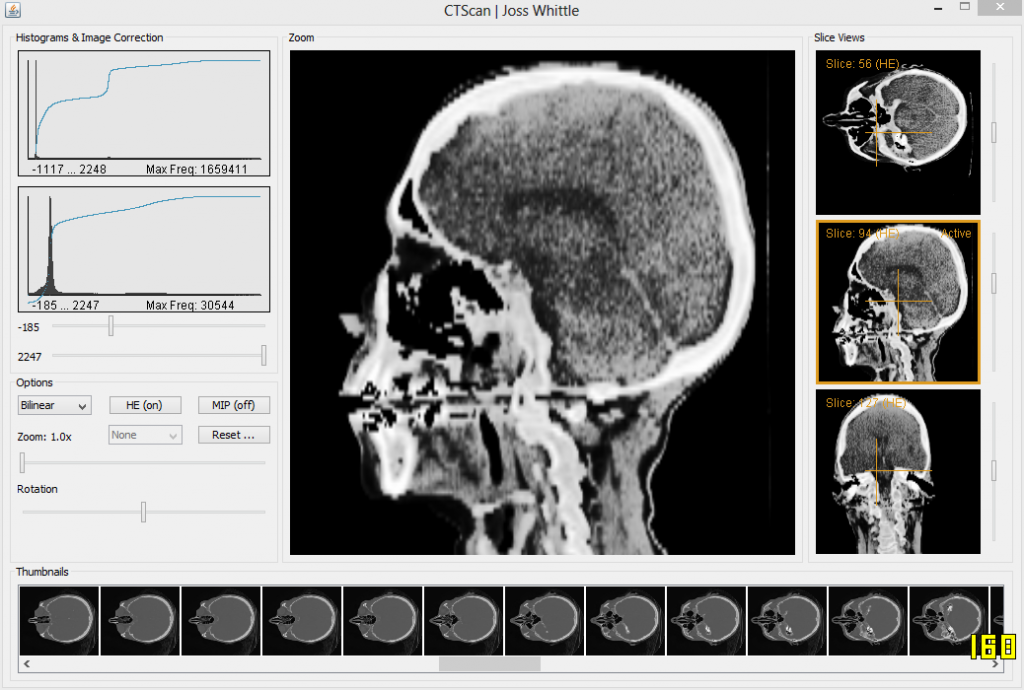
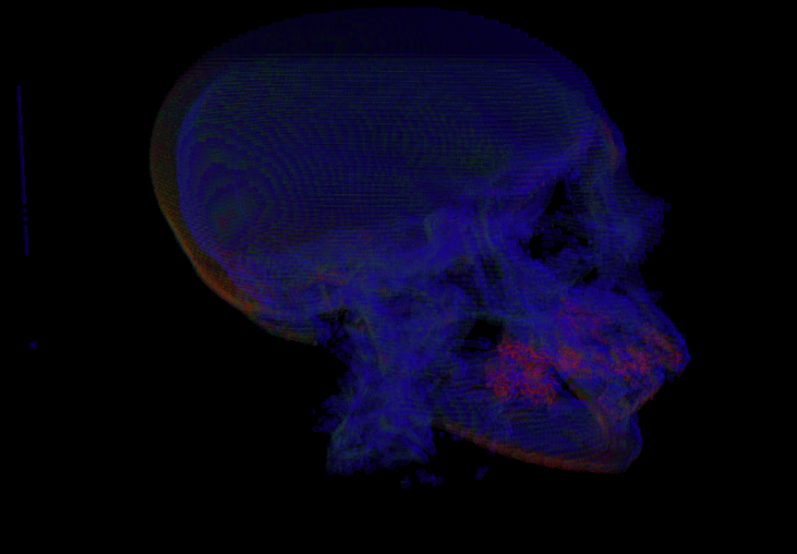
Voxels are useful for displaying other kinds of volume data too. CT Scans are medical images which capture 3D density plots of a patient’s body. By capturing density at each location throughout the scanned tissue the data can be replayed using a computer to literally look inside the body and see where possible irregularities and illness may reside.
2nd year CT Scan coursework
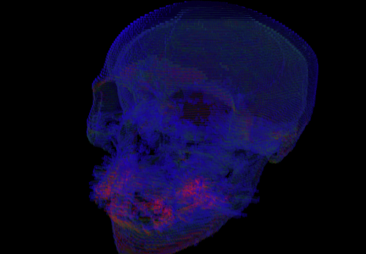
In my second year at university I was given a Computer Graphics coursework to read in and display the data for a CT Scan. It was very low resolution, only 256 * 256 * 113 voxels in size but it worked well for the purposes of the coursework which was simply to demonstrate the ability to parse the volume data into usable slices (not that hard). There were several bonus sections to the project such as histogram equalization and density bounding to eliminate tissue we didn’t care about. Another one of the bonuses was for rendering the volume data in 3D with a hint of using trilinear interpolation. At the time the work load we were under was horrendous due to the year long group engineering project, so while I eagerly completed all of the other bonuses I just didn’t have time to get 3D working. Until now.
It’s not pretty, and in fact it’s really not pretty when you make it 3D due to the low input resolution of the scan. But there it is! The same CT Scan now rendered in 3D in OpenGL. I used the Java bindings for OpenGL (JOGL) so I could use the same loader code I wrote in 2nd year to parse the binary CT file into a 3D array of shorts.
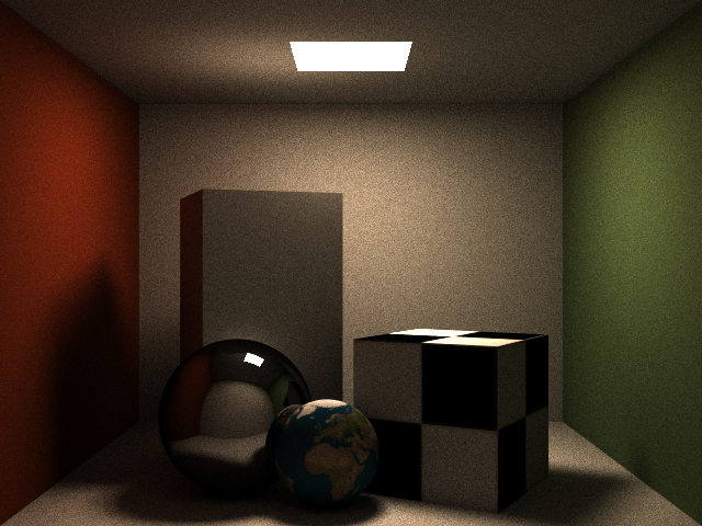
So I’m back to working on this again.. It’s a lot better than before but it’s not perfect. I’m still using unweighted samples during path generation and I am still generating a fresh path (highly randomized in path traced -> light traced construction) for every sample. Because of this the noise that still persists in the image above will never feasibly go away. Today I plan to look at “Multiple Importance Sampling” a lot more in depth.
This morning I was neck deep in code writing a Bi-Directional Path Tracer and this evening I’m building a 3D Printer out of Lego… If only I had the attention span and patience to actually finish a project before starting another. Oh well.
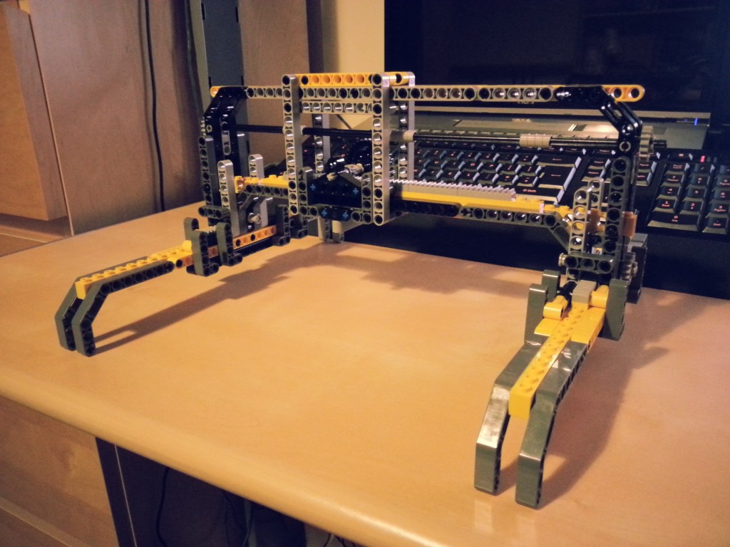
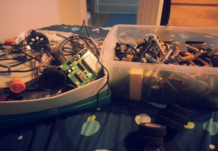
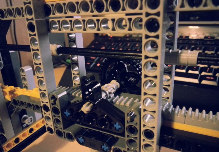
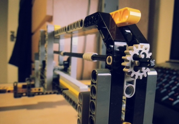
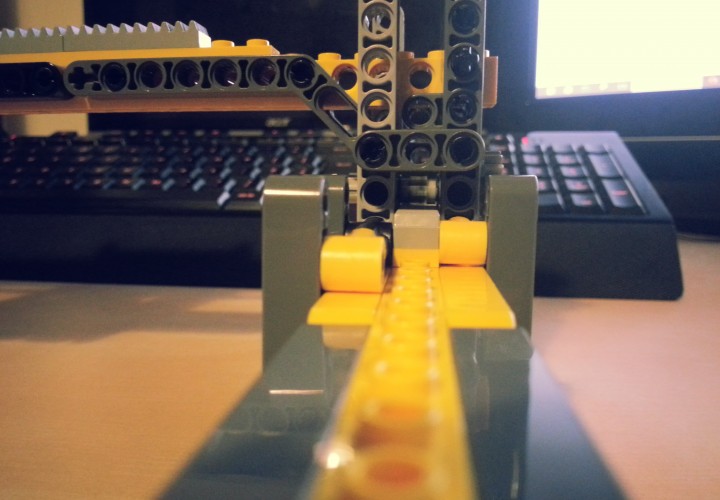
Continuing on from my previous post, in the end I actually trudged down the garden to the shed and pulled all my old Lego Technic out of storage. A quick session of sorting out what kind of bits I had and then thinking about how I could adapt the designs I had bad in CAD to work within the limitations of those parts I decided to just delve in and see what I could make. I was surprised at how much Lego I actually had, but then again my family was always really into Lego & Meccano; and I was quite fond of Knex too come to think of it.
As it turns out the amount of Lego Technic I do have is more than enough to build the frame and mechanics for the first two axes of the Printer. There are some crucial areas however, where I have ran out of very important bits needed for this specific application. For instance the flat toothed strips used to make the tracks for the carriages to walk on were in short supply. I managed to place them on the top carriage such that the X axis gondola can fully utilize them with no waste. However after laying the X axis track there were only four of the tooth strips left; meaning that for now each side of the Y axis tracks only has two toothed segments. I’ll need to get more of them to finish the Y axis along with some gears and extra chain for connecting the cross axle to the walking gears.
It was possible to make some improvements to the initial design during this first build step. Namely the Y axis walker which holds the X axis and gondola is considerably thinner than in the original design, however the gondola still has nearly the same amount of movement. This was achieved partly by making the two connections to the Y axis tracks thinner than their originals, which allows the gondola to travel much closer to the ends of the track. The condensed size also keeps the frame more rigid than a wider variant would have been.
A month or so before I found out I would be starting my PhD in October I was still under the impression that I would be doing an MEng and with it another dreaded dissertation project. This time however, the project would be to do with a software engineering problem, as opposed to last years which could be either industrial, research based, or software engineering.
After much deliberation looking at the shockling short list of projects I decided that I didn’t particularly want to spend a year working on any of them. Not that they were all bad per say, just that if you’re going to spend a whole year working on a single project you best be sure you care about it.
One thing that did interest me about the projects however, a few of them involved using Arduino and embedded systems. This got me thinking, what could I do with Arduino that I could propose as my own project idea? Inspiration didn’t take long, that night I stumbled across this gem while watching random videos on Youtube.
I loved it straight off, to use Lego Technic and Mindstorm NXT to create a working CNC machine! Perhaps this would make a good masters project?
Alas the the project is very much closed source and even the designs for the machine are not available.
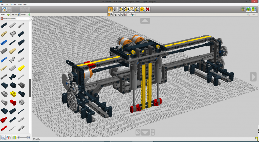
I have however, been able to reproduce the design of the machine and it’s mechanics in 3D using Lego’s 3D Autocad software, Lego Digital Designer. This was a long and painstaking process of taking screenshots of the above video and blowing them up to see the finer details (thank god for 1080p Youtube streaming) and mixing this with my methodology for how I would build this machine if I was given an unlimited set of lego. The result of my reconstruction can be seen below. While it is not a complete build (I omitted the static Y-Axis track that the carriage pictured would ride on), it is the technical majority of the machine.
I believe that this design can even be further improved upon to use less lego while allowing for a larger and more stable device to be constructed. The main limitation with increasing the track size of the device in it’s current configuration is finding a way to proportionally increase the size of the Z-Axis (vertical). Currently this axis uses two Lego Technic linear actuators to move the tool carriage up and down. However, the actuators have a fixed and limited range of climb which cannot be altered. A difference approach might be to use a threaded bar configuration to make a track which moves up and down instead with a small tensioning system to remove vibration and slack from the printing.
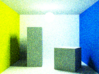
After a minor crisis that I am horribly unprepared to start my PhD in October I thought I’d try to delve back into the world of graphics with something simple (ha). I decided to try and extend my Java Path Tracer to support a rendering mode for Bi-Directional Path Tracing. Something which I now realize is easier said than done. Ideally if I had had the time I would have introduced Bi-Directional Path Tracing (BDPT) to my dissertation project last year; however, I simply never had the time to wrap my head around all the mathematics so I left it out.
The image above was rendered at 640 x 480 but I have downsampled the image here to 320 x 240 to make up for the fact I was only able to render 100 samples before my computer BSOD’d. That’s right, because if you can make a Java program cause a BSOD then you know something is terribly amiss. My theory is that it’s simply too much recursion for the JVM. Even though I am running the 64bit version with an increased memory quota the stack for function calls is still (annoyingly) a memory limited 32bit stack. And seeing as this is just a toy project I am working on whenever I start to panic about next year it doesn’t seem worth spending the time to convert the whole thing to an iterative renderer from a recursive one.
I’ve been meaning to do it for a while but I have finally gotten around to making a Template for OpenCL & OpenGL Projects in Visual Studio 2012.
The host application is written in C++ using GLew and freeGLUT to interface with OpenGL, and the Amd APP SDK to interface with OpenCL as I am running a ATI 5850 GPU. Building upon the template is fast and easy and really comes down to just a few core functions which differ for each program. Below is a simplified version of the functions each program must implement.
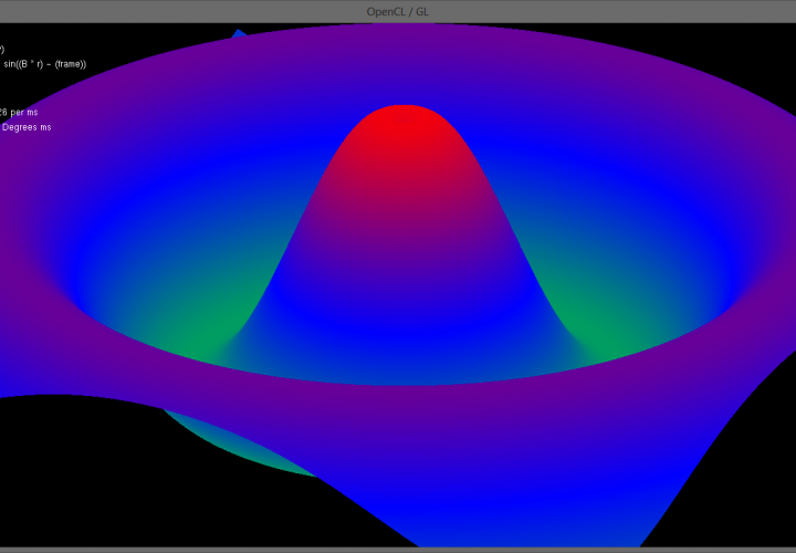
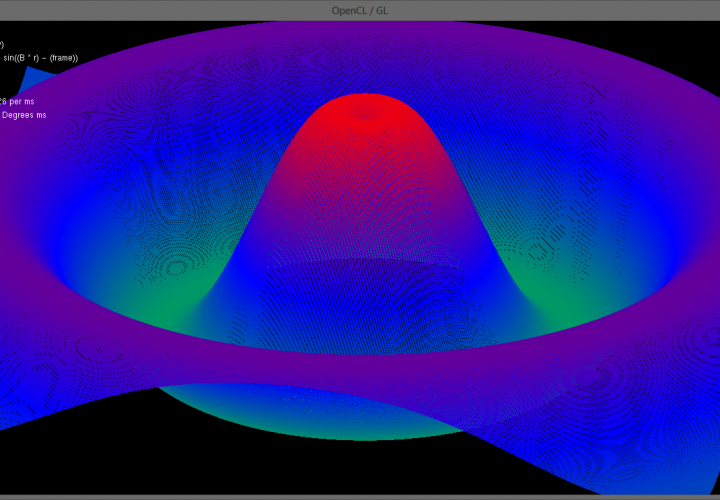
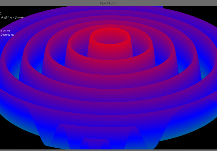
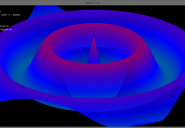
Using this frame as a base to build off of I was able to quickly and easily get a demo running. The program in the video above and the images below generates a 1000 * 1000 (1 million) vertex triangular mesh and displays an exponential sine function over it. At each frame OpenCL computes the 3D location of all 1,000,000 points in the mesh which OpenGL then renders. Due to the massively paralleled nature of the OpenCL update code frame rates exceeding 100 frames per second are achieved! (In the video Fraps capped the frame rate at 30fps for smooth capture)
Below is a simplified version of the SineMesh Demo, most of the work is performed in the initialization phase to create the 1000 * 1000 mesh and link the triangles together. The program could be made a lot more efficient if the triangle linking phase was done such that it creates a Triangle Strip as opposed to the current Triangle List. A strip has the benefit of chaining touching triangles together to save the number of vertices which need to be stored in the linking array.